
Interpreting the Raw EEG: Four Montages
- Fred Shaffer
- Jun 20, 2025
- 16 min read
Updated: Jul 30, 2025

Montages
The analysis of electroencephalographic (EEG) recordings is deeply dependent on the montage selected for data presentation.

A montage defines the configuration in which electrodes are referenced to one another, thereby shaping the electrical field and influencing the visibility, morphology, and localization of cerebral signals.
EEG montages combine derivations, which are pairs of electrodes. A derivation assigns two electrodes to an amplifier's inputs 1 and 2. For example, Fp1 to O2 means that Fp1 is placed in input 1 and O2 in input 2.
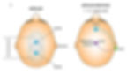
A montage, also known as an array, combines derivations to record EEG activity (Thomas, 2007). Below is a referential bipolar montage that places two active electrodes on the scalp and a ground (G) on the ear or mastoid. Bipolar montage graphic adapted from Demos (2019).
All montages compare EEG activity between one or more pairs of electrode sites.
The choice of montage does not alter the raw cortical electrical activity itself, but rather filters, enhances, or diminishes aspects of it based on the spatial relationship between electrodes and the dipolar sources within the brain.
In this extended analysis, we will examine the four EEG montages used to analyze the same epoch—longitudinal bipolar, transverse, average reference, and Cz reference—discussing in detail their configurations, technical strengths, inherent limitations, and their influence on the interpretation of the same electrophysiological event.
Best Practices from the American Clinical Neurophysiology Society Guideline 3 (2016)
The Committee reaffirms the statements pertaining to montages set forth previously in the Guidelines of the American Clinical Neurophysiology Society (ACNS) and that are paraphrased as follows:
(a) that no less than 16 channels of simultaneous recording be used, and that a larger number of channels be encouraged,
(b) that the full 21 electrode placements of the 10-20 system be used,
(c) that both bipolar and referential montages be used for clinical interpretation,
(d) that the electrode derivations of each channel be clearly identified at the beginning of each montage,
(e) that the pattern of electrode connections be made as simple as possible, and that montages should be easily comprehended,
(f) that the electrode pairs (bipolar) preferentially should run in straight (unbroken) lines and the interelectrode distances kept equal,
(g) that tracings from the more anterior electrodes be placed above those from the more posterior electrodes on the recording page, and
(h) that it is very desirable to have some of the montages comparable for all EEG laboratories.
2.2 The Committee recommends a “left above right” order of derivations, i.e., on the recording page, left-sided leads should be placed above right-sided leads for either alternating pairs of derivations or blocks of derivations. This recommendation coincides with the prevailing practice of most EEG laboratories, at least in North America and in many other areas.
Longitudinal Bipolar Montage: Configuration, Strengths, and Limitations
The longitudinal bipolar (double banana) montage, is one of the most widely employed configurations in clinical electroencephalography. It consists of a series of bipolar derivations arranged in parallel, linking electrodes from the frontal to the occipital poles along the midline and lateral chains of the scalp. For example, one chain may include the derivations Fp1–F3, F3–C3, C3–P3, and P3–O1, forming a continuous pathway along the left hemisphere. A mirror set is applied on the right: Fp2–F4, F4–C4, C4–P4, and P4–O2. These pairings create an electrical map that is optimal for detecting activity propagating along the anterior-posterior axis of the cerebral cortex.
Strengths
The primary strength of this montage lies in its capacity to enhance phase reversals, which are the inversion points of waveform polarity along the bipolar chain and serve as a crucial diagnostic cue for localizing the maximum field of a focal discharge. When a sharp wave or spike occurs in a cortical region sampled between two electrodes, the voltage gradient between them becomes pronounced, resulting in an easily identifiable phase reversal that pinpoints the site of maximal activity. This makes the montage particularly adept at detecting focal epileptiform activity, especially when it is organized along the sagittal plane (Niedermeyer & da Silva, 2005). The montage is also intuitive and standardized, which facilitates inter-reader reliability across clinical institutions.
Limitations
However, the longitudinal bipolar montage is not without limitations. Because each channel is composed of a bipolar derivation, activity that is spatially generalized across adjacent electrode pairs—such as in generalized epileptic discharges or diffuse slowing—may be attenuated or even cancelled out, particularly if it appears in phase across a chain. Additionally, activity that is vertically or obliquely oriented relative to the anteroposterior axis may be poorly resolved due to the montage’s directional bias. Furthermore, the montage may be less sensitive to activity with a deep cortical origin, such as from mesial temporal structures, which may not produce robust potentials at the scalp surface.
Transverse Montage: Configuration, Strengths, and Limitations
The transverse montage, or coronal bipolar montage, is an alternative bipolar configuration in which electrodes are linked across the coronal plane of the scalp, from lateral to medial or from one hemisphere to the other. For example, a typical chain might include F7–F3–Fz–F4–F8 across the frontal row, followed by a second chain of T3–C3–Cz–C4–T4 at the central level, and posteriorly T5–P3–Pz–P4–T6, extending through the parietal and temporal regions. These linkages are designed to visualize activity spreading horizontally across the hemispheres or in a left-right configuration.
Strengths
The transverse montage is especially advantageous in situations where lateralization is of clinical concern. It is often used as a complementary montage to the longitudinal bipolar in epilepsy workups, as it can delineate whether a waveform or discharge is restricted to one hemisphere, crosses the midline, or is more pronounced on a particular side. By emphasizing horizontal field distribution, the transverse montage improves detection of temporal lobe discharges, which often extend laterally and may appear less prominent in a longitudinal montage. Moreover, the transverse montage is adept at highlighting hemispheric asymmetries in background rhythm and interictal epileptiform activity, offering a different spatial perspective than traditional sagittal derivations.
Limitations
Nonetheless, this montage also presents specific challenges. Its less common use makes it less familiar to many general neurologists, requiring a higher level of interpretive skill and spatial visualization. The absence of anterior-posterior connections can obscure phase reversals along that axis, making it less effective for localizing discharges that originate in midline or parasagittal regions. In addition, the reliance on lateral electrodes introduces greater sensitivity to artifact from facial and temporal muscle activity, which can be a confounding factor in certain recordings.
Average Reference Montage: Configuration, Strengths, and Limitations
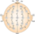
The average reference montage is conceptually different from bipolar montages in that it is constructed by referencing each active electrode to the mean potential of all scalp electrodes. Mathematically, the signal from each electrode is recalculated as the difference between that electrode and the averaged signal from the full array. The underlying assumption is that the sum of all scalp-recorded potentials approximates zero, creating a neutral reference. In practice, this configuration is implemented in modern digital EEG systems using real-time computational averaging across electrodes, excluding those contaminated by artifact or poor contact. The image below was adapted from Lopez et al. (2017). In most cases, the midline electrodes are also included in these calculations.

Strengths
The primary advantage of the average reference montage is its reference-free nature, which provides a theoretical spatial neutrality. This can be particularly useful in visualizing diffuse, low-amplitude cerebral activity, including generalized spike-wave discharges, slow wave abnormalities, and subtle background fluctuations. Because each electrode is displayed with respect to the same computed reference, spatial comparisons across channels are more direct, making this montage highly valuable in quantitative EEG (qEEG) and source localization studies (Fisch, 1999).
Limitations
However, the montage is also highly susceptible to contamination by a single noisy electrode. If one or more electrodes have a high amplitude artifact (e.g., due to muscle or movement), or localized high amplitude EEG source such as rhythmic alpha or transient discharges, this can affect the computed average, thereby distorting every channel in the montage, making it appear that the the feature is present in other electrodes, often far from the original source, such as frontal alpha where none exists.
Moreover, the assumption that the average voltage equals zero is only valid when electrodes are evenly distributed and the cortical activity is spatially balanced—conditions rarely met in practice. In the presence of significant focal abnormalities, the average reference can over- or under-estimate the true field of the activity and may even introduce artifactual inversions or misleading asymmetries (Loddenkemper et al., 2014).
Cz Reference Montage: Configuration, Strengths, and Limitations
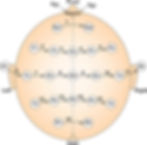
The Cz reference montage is a unipolar configuration in which every scalp electrode is referenced to a single, fixed electrode located at the vertex of the scalp—Cz, the central midline location. This configuration is straightforward and provides consistent spatial orientation for each channel, allowing the reader to compare the amplitude and waveform morphology at different sites relative to a central standard. It is commonly used in event-related potential (ERP) studies, sleep scoring, and pediatric EEG, where ease of interpretation and temporal clarity are prioritized. The image below was adapted from Lopez et al. (2017). In most cases, the midline electrodes are also included in these calculations.

Strengths
One of the key benefits of the Cz reference montage is its ability to reveal lateralized discharges. Because Cz is equidistant from the hemispheres, discharges arising from left or right hemispheres produce strong voltage differences and clear waveforms. The fixed reference also facilitates temporal alignment of discharges, which is useful in assessing spike timing, propagation patterns, and hemispheric synchrony.
Limitations
Nonetheless, Cz is a problematic reference point for activity that originates near the vertex itself, such as discharges from the supplementary motor area, parasagittal cortex, or midline regions. Since the reference is physically close to the source, the recorded potential difference may be minimal or even absent, leading to false negatives. Furthermore, Cz may itself pick up cortical signals, which undermines the assumption of a neutral reference, particularly during periods of midline activation. This limitation becomes particularly relevant when interpreting generalized or midline spike-wave complexes or high-frequency sleep spindles that originate near central sites (Niedermeyer & da Silva, 2005).
Comparative Interpretation of EEG Recordings Across Montages
Each of the four EEG recordings displays the same epoch of neural activity under different montage configurations. The tracings show alternating periods of eye opening and eye closure, with clear electrophysiological consequences. Following eye closure, a robust posterior dominant rhythm (PDR) becomes evident, characterized by symmetrical, sinusoidal waveforms in the 8–12 Hz alpha frequency range, with maximal amplitude over the occipital electrodes (O1 and O2). Additionally, there are discrete, sharply contoured bursts that emerge superimposed on the background alpha rhythm, particularly over the right occipital region. These bursts may represent benign occipital variants or could reflect intermittent epileptiform discharges, depending on clinical correlation and additional context.
The Longitudinal Bipolar Montage: Montage
In the longitudinal bipolar montage, this PDR is classically visualized with clarity. The posterior derivations—especially P3–O1 and P4–O2—demonstrate the expected waxing and waning of alpha activity associated with eye closure and opening. The sharply contoured bursts appear most distinct in the P4–O2 channel, with a clear phase reversal at O2, indicative of a localized right occipital focus. This montage best demonstrates the polarity shift and helps localize the discharge to the occipital pole. This longitudinal bipolar montage graphic © The Atlas of Adult Electroencephalography.

Transverse Montage
The transverse montage offers complementary information. The same alpha rhythm appears but with a slightly altered topography. Here, the asymmetry becomes more evident, as the right-sided discharges demonstrate greater amplitude and sharper morphology in the O2–P4 and T6–P4 channels. The montage’s sensitivity to horizontal propagation accentuates the lateral dominance, reinforcing the impression of a right occipital source. Temporal electrodes also show increased involvement, which may indicate posterior temporal spread or represent volume conduction from occipital sources. This transverse montage graphic © The Atlas of Adult Electroencephalography.

Average Reference Montage
The average reference montage depicts the general spatial distribution of the PDR, but the sharp transients appear attenuated. In O2–AVG, the alpha rhythm remains visible, but the burst-like activity lacks the crisp, sharply contoured morphology seen in the bipolar configurations. The montage provides a global perspective, making it useful for detecting background symmetry and diffuse abnormalities, but it obscures the focal nature of the discharges. Without a clear reference point, it is difficult to identify phase reversals or definitively lateralize the activity. This average reference montage graphic © The Atlas of Adult Electroencephalography.

Cz Reference Montage
In the Cz reference montage, the PDR is again visible, with right-sided discharges producing prominent waveforms in the O2–Cz channel. However, due to the proximity of Cz to midline structures, the relative amplitude of central discharges is diminished. While right occipital bursts remain detectable, the resolution of activity arising near midline is limited. This montage provides a lateralized but less spatially specific representation of the abnormal activity, which may be insufficient on its own for confident localization. This Cz reference montage graphic © The Atlas of Adult Electroencephalography.

Clinical Implications
Taken together, the EEG tracings across these four montages depict a physiologic alpha rhythm emerging with eye closure, alongside intermittent sharply contoured activity localized to the right occipital region. The morphology, timing, and lateralization of the latter suggest potential interictal epileptiform discharges, possibly arising from a right occipital epileptogenic zone. However, further confirmation would require clinical correlation, photic stimulation testing, and perhaps additional recordings during drowsiness or sleep.
The longitudinal bipolar and transverse montages are most effective in demonstrating the key features—clear localization, polarity, and sharp morphology—whereas the average reference montage contributes more to an assessment of symmetry and background integrity. The Cz montage offers a reliable lateralized view but lacks optimal resolution for midline sources. Understanding the comparative strengths of each montage allows for more precise interpretation and guides clinical decision-making in epilepsy diagnosis and beyond.
Conclusion
In clinical electroencephalography, the montage used to display EEG data fundamentally shapes how brain activity is visualized and interpreted. Each montage—whether longitudinal bipolar, transverse, average reference, or Cz reference—has distinct strengths and limitations. However, an essential feature of modern EEG analysis is that clinicians are not limited to a single montage when evaluating an EEG recording. Because digital EEG systems preserve the raw voltage potential at each electrode, clinicians can reconfigure how these signals are displayed by applying different montages to the same epoch of data. This process, known as re-montaging, allows for a more complete and nuanced understanding of the recorded brain activity.
Re-montaging enables clinicians to re-express the same underlying electrical signals in different spatial contexts. A particular waveform or discharge may appear more prominent, localized, or sharply contoured in one montage and more diffuse or less distinct in another. For example, a spike that is clearly localized with a phase reversal in a longitudinal bipolar montage may appear attenuated or blended with surrounding activity in an average reference montage. Conversely, generalized discharges may be more clearly appreciated in referential montages, such as the average or Cz reference, whereas bipolar montages may obscure them due to cancellation effects.
Clinicians re-montage not only to improve visualization of specific events but also to clarify ambiguous findings. A sharply contoured waveform seen in a bipolar montage can be cross-checked in a referential montage to determine whether it reflects true cortical activity or a muscle artifact. Similarly, rhythmic slowing that appears focal in one configuration may prove to be part of a more diffuse process when re-displayed using another montage. This comparative approach helps avoid misinterpretation, particularly in cases where benign variants or technical artifacts could otherwise be mistaken for pathologic activity.
Re-montaging also supports more accurate localization. Some montages are aligned along specific anatomical axes and are therefore more sensitive to discharges propagating in particular directions. The longitudinal bipolar montage, for instance, follows the anterior-posterior axis and is well-suited for identifying phase reversals in that orientation. However, it may not capture lateral propagation across hemispheres as effectively as the transverse montage. By re-montaging into both configurations, a clinician can more precisely triangulate the source of epileptiform discharges or assess whether a waveform is confined to one hemisphere or crosses the midline.
Moreover, the ability to re-montage is indispensable in certain clinical scenarios. When evaluating patients for focal epilepsy, the need to localize seizure onset to a particular lobe or hemisphere is paramount. Re-montaging can reveal subtle asymmetries or focal features that might not be visible in the original display. In cases of suspected encephalopathy, re-montaging into an average reference montage may better demonstrate diffuse slowing or triphasic waves. In sleep EEGs, where vertex sharp waves and sleep spindles may be crucial, the choice of reference becomes especially important, as certain references may suppress or distort these midline phenomena.
Digital EEG systems have made re-montaging straightforward and immediate. Rather than being constrained by the montage selected during acquisition, clinicians can explore different configurations at any point during interpretation. This flexibility is endorsed by the American Clinical Neurophysiology Society, which recommends the use of both bipolar and referential montages and emphasizes the need for clarity, simplicity, and interpretability in montage design. Their guidelines further encourage the use of at least 16 recording channels and the full complement of 10–20 system electrodes to ensure comprehensive spatial sampling and re-montage capability.
Ultimately, the purpose of EEG is to accurately identify and characterize brain activity—whether normal or abnormal, diffuse or focal, transient or rhythmic. No single montage can fully reveal all aspects of this activity. By using multiple montages to re-express the same epoch of EEG, clinicians can compensate for the spatial and referential limitations of individual configurations. This approach allows for the confirmation of findings across montages, facilitates more precise localization, and strengthens diagnostic confidence. The ability to re-montage is not just a technical convenience—it is a critical component of rigorous EEG interpretation and a powerful tool in clinical neurophysiology.
Key Takeaways
Montage choice influences EEG interpretation by shaping how electrical activity is visualized, localized, and differentiated.
No single montage is sufficient for comprehensive analysis; each has unique strengths and limitations.
Re-montaging allows clinicians to re-express the same data using different configurations to clarify waveform origin, morphology, and spread.
Bipolar montages excel at localizing focal discharges, while referential montages better highlight generalized or diffuse patterns.
The systematic use of multiple montages improves diagnostic accuracy and aligns with clinical guidelines for best EEG practices.

Glossary
10–20 System: a standardized method for electrode placement on the scalp used in EEG, ensuring reproducibility and anatomical consistency across patients and recording systems.
alpha rhythm: a posterior-dominant EEG waveform in the frequency range of 8–12 Hz, typically seen during wakeful rest with eyes closed.
amplitude: the height of an EEG waveform, measured in microvolts (µV), reflecting the strength of the electrical signal between two electrodes.
anterior-posterior axis: the front-to-back orientation of the head, commonly used in EEG electrode arrangements and montages, especially in longitudinal bipolar configurations.
artifact: non-cerebral electrical activity recorded on EEG, often from muscle movement, eye movement, or external sources, which can interfere with interpretation.
average reference montage: an EEG referencing technique where each electrode is referenced to the arithmetic mean of all scalp electrode potentials; used to highlight focal activity and reduce common signals.
bipolar montage: a montage in which each EEG channel represents the voltage difference between two adjacent scalp electrodes.
channel: a single EEG tracing derived from a pair of electrodes (a derivation), used to display the voltage difference over time.
clinical correlation: the integration of EEG findings with clinical signs and symptoms to arrive at a diagnosis or guide treatment.
cortical activity: electrical signals generated by neurons in the cerebral cortex, recorded on the scalp as EEG waveforms.
Cz: the central midline electrode in the 10–20 system, often used as a common reference point in unipolar montages.
derivation: a pair of electrodes used in EEG to create a single channel, showing the voltage difference between two points on the scalp.
diffuse slowing: a generalized reduction in EEG frequency across multiple regions of the brain, often indicative of metabolic or structural brain dysfunction.
dipolar sources: brain-generated electrical fields that produce opposing voltages detectable at the scalp; critical in EEG localization.
electrode: a conductive sensor placed on the scalp to record electrical activity from the brain.
epoch: a time segment of EEG recording, usually lasting a few seconds, used to examine waveform characteristics within a specific interval.
epileptiform discharges: abnormal, paroxysmal waveforms such as spikes or sharp waves, typically associated with epilepsy.
event-related potentials (ERP): brain responses that are the direct result of a specific sensory, cognitive, or motor event, recorded as time-locked changes in EEG.
focal activity: EEG signals that originate from a localized area of the brain, as opposed to generalized activity.
generalized discharges: EEG abnormalities that occur simultaneously and symmetrically across both hemispheres.
hemisphere: one half of the brain (left or right); EEG analysis often involves comparing electrical activity between hemispheres.
interelectrode distance: the physical spacing between two electrodes used in a derivation, which influences signal resolution and spatial sampling.
interictal epileptiform discharges: spikes or sharp waves that occur between seizures, commonly used as markers for epileptic foci.
lateralization: the identification of whether EEG activity is more prominent in one hemisphere than the other.
localization: the process of determining the origin of EEG activity within the brain, often aided by montage selection and waveform characteristics.
longitudinal bipolar montage: a bipolar montage where electrodes are connected front-to-back along the anterior-posterior axis; also known as the "double banana" montage.
montage: the configuration of electrode pairings used to display EEG data, which affects how electrical activity is visualized and interpreted.
morphology: the shape and structure of EEG waveforms, including sharpness, symmetry, and duration, which help determine normal versus abnormal activity.
occipital region: the posterior part of the scalp corresponding to the occipital lobe, often showing alpha rhythm and visual-related activity.
parasagittal cortex: the cortical regions near the midline of the brain; activity here can be difficult to detect depending on the montage used.
phase reversal: a change in polarity between adjacent electrodes in a bipolar montage, indicating the likely location of maximal voltage and aiding in source localization.
PDR (Posterior Dominant Rhythm): a normal EEG rhythm typically seen in awake individuals with eyes closed; centered in the occipital region and in the alpha frequency band.
polarity: the direction of waveform deflection (positive or negative) in EEG, relevant for determining the source and direction of electrical activity.
re-montaging: the process of re-displaying EEG data using a different montage configuration, allowing clinicians to view the same recorded electrical activity from alternative spatial perspectives to enhance interpretation, localization, and artifact differentiation.
sagittal plane: a vertical plane that divides the body into left and right sides; sagittal orientation is important in certain EEG montages.
spatial resolution: the ability of an EEG montage to distinguish electrical activity arising from different areas of the brain.
temporal lobe: a region of the brain located laterally, often involved in seizure disorders and particularly well-assessed using transverse montages.
topography: the spatial distribution of EEG activity over the scalp, which helps localize and characterize cerebral function and dysfunction.
transverse montage: a bipolar EEG montage that links electrodes horizontally across the head, providing sensitivity to lateralized and horizontal propagation of activity.
unipolar montage: a montage in which each electrode is referenced to a single common electrode (e.g., Cz or average), unlike bipolar configurations.
voltage gradient: the difference in electrical potential between two electrodes, reflected in the amplitude of the EEG waveform.
waveform: a visual representation of electrical activity over time in the EEG, characterized by frequency, amplitude, and morphology.
References
Acharya, J. N., Hani, A. J., Thirumala, P. D., & Tsuchida, T. N. (2016). American Clinical Neurophysiology Society Guideline 3: A Proposal for Standard Montages to Be Used in Clinical EEG. Journal of Clinical Neurophysiology: Official Publication of the American Electroencephalographic Society, 33(4), 312–316. https://doi.org/10.1097/WNP.0000000000000317
Carvalhaes, C., & Acacio de Barros, J. (2014). The surface Laplacian technique in EEG: Theory and methods. International Journal of Psychophysiology, 97(3), 174–188.
Demos, J. N. (2019). Getting started with neurofeedback (2nd ed.). W. W. Norton & Company.
Fisch, B. J. (1999). Spehlmann's EEG Primer. Elsevier.
Gordon, E., & Rzempoluck, E. (2004). EEG neuroimaging techniques. International Journal of Neuroscience, 114(10), 1343–1371.
López, S., Gross, A., Yang, S., Golmohammadi, M., Obeid, I., & Picone, J. (2016). An analysis of two common reference points for EEGs. IEEE Signal Processing in Medicine and Biology Symposium, 2016, 10.1109/SPMB.2016.7846854. https://doi.org/10.1109/SPMB.2016.7846854
Niedermeyer, E., & da Silva, F. L. (2005). Electroencephalography: Basic Principles, Clinical Applications, and Related Fields (5th ed.). Lippincott Williams & Wilkins.
Nunez, P. L., & Srinivasan, R. (2006). Electric Fields of the Brain: The Neurophysics of EEG (2nd ed.). Oxford University Press.
580.2004.12104.x
Valentine, D. (2020). Learning EEG.
About the Author

Fred Shaffer earned his PhD in Psychology from Oklahoma State University. He earned BCIA certifications in Biofeedback and HRV Biofeedback. Fred is an Allen Fellow and Professor of Psychology at Truman State University, where has has taught for 50 years. He is a Biological Psychologist who consults and lectures in heart rate variability biofeedback, Physiological Psychology, and Psychopharmacology. Fred helped to edit Evidence-Based Practice in Biofeedback and Neurofeedback (3rd and 4th eds.) and helped to maintain BCIA's certification programs.
Support Our Friends


